A valley bottom is a low lying area of a valley comprised of both the stream channel and contemporary floodplain. This area also represents the maximum possible extent of riparian areas of the streams associated with the valley bottom. VBET uses a minimum of two input datasets, a Digital Elevation Model (DEM) and a stream network to create a polygon representing the valley bottom. This valley bottom polygon is then used as an extent for the riparian condition analyses in this toolbox.
Pre-Processing
Stream network preparation: a stream network for the area of interest must first be prepared. See NHD Network Builder Tool. DEM preparation: A DEM should be downloaded and clipped to the extent of the analysis area (ie match the extent of the stream network). The DEM should have a projected coordinate system that matches the selected coordinate system for the stream network. Drainage area raster: optionally, a flow accumulation raster can be derived, and converted to a drainage area raster (units of square kilometers) to be used in the VBET tool. If this is not done beforehand, it will be performed automatically upon running the tool. Once the inputs are prepared, you should organize them into a project structure by running the Build VBET Project tool in the toolbox. You will be prompted to select a “project folder,” which is a location to store all inputs, outputs and metadata related to the VBET project. You may then select the inputs you plan to use. You may select multiple of any input. For example, you may wish to derive one valley bottom using a 10 m DEM, and another using 1 m LiDAR. Both datasets can be added to the project at this point. Later, when running the VBET tool, you can run the tool multiple times selecting different input datasets. At least one of each required input must be added to the project using this tool. Important: when setting up the project, there cannot be any spaces in any path names. Make sure underscores are used instead of spaces.
VBET Tool Parameters
- Project Name (optional): you may name the project. This will be recorded in the metadata xml.
- Watershed HUC ID (optional): you may add the USGS Hydrologic Unit Code if you are using these watershed boundaries. This will be recorded in the metadata xml.
- Watershed Name (optional): you may add the name of the project watershed. If you are using Hydrologic Unit Codes, this should be the HUC Name that corresponds to the HUC ID. This will be recorded in the metadata xml.
- Select Project Folder: select the project folder that was populated using the Build VBET Project tool. Note - We suggest running the tool in a folder path with no spaces in the name (e.g.
c:\0_VBET\MyVBETOutputas opposed toc:\0 VBET\My V-BET Output\, which can cause ArcGIS geoprocessing problems during write to disc operations). - Input DEM: select the desired DEM within the project folder.
- Input Stream Network: select the desired stream network within the project folder. This network must consist of many segments (ie it cannot be a single dissolved feature). NHD layers are naturally segmented.
- Input Drainage Area Raster (optional): if you opted to create a drainage area raster beforehand and added it to the project, select it from within the project folder. Name Valley Bottom Output: choose a name for the valley bottom output (which will be stored in the Analyses in the project file). -** High Drainage Area Threshold**: enter a drainage area value (square km). Streams whose upstream drainage area is greater than this value will be considered the “large” portion of the network, whose maximum valley bottom width will be represented with the “Large Buffer Size” parameter. The default value is 250.
- Low Drainage Area Threshold: enter a drainage area value (square km). Streams whose upstream drainage area is less than this value will be considered the “small” portion of the network, whose maximum valley bottom width will be represented with the “Small Buffer Size” parameter. Streams whose upstream drainage area is between the high and low drainage area thresholds will be considered the “medium” portion of the network and their maximum valley bottom width represented by the “Medium Buffer Width” parameter. The default value is 25.
- Large Buffer Size: the large buffer size represents half of the width of the widest portions of the valley (generally broader alluvial valleys) in the lower portion of the area of analysis. This number can be obtained using the measure tool in either ArcMap or Google Earth prior to running the tool.
- Medium Buffer Size: the medium buffer size represents half of the width of the valley in areas where confined headwater streams transition to slightly wider valleys where they become partly confined. Again, this number can be obtained beforehand in a GIS. Look for areas in the area of analysis where confined headwaters transition into partly confined valleys to make the measurement.
- Small Buffer Size: the small buffer size represents half the width of the valley in confined headwater type settings. Measurements can be made prior to running the tool to obtain this value. A value of around 25 meters seems to work well in most cases.
- Minimum Buffer Size: in some areas the slope is to steep or channel too confined to pick up the valley bottom. To ensure a continous valley bottom polygon as an output, the minimum buffer fills in these gaps. A value of ~8 to 10 meters is generally appropriate.
NOTE: the buffers represent the maximum extent of the valley bottom for each of the given settings. If the output is going to be manually edited to achieve higher accuracy, it is generally better to slightly underestimate the valley bottom and add to it than it is to overestimate the valley bottom and trim off of it. The small buffer and minimum buffer (headwaters) are the exceptions to this rule. Generally in these areas, the stream network is not accurate enough to perfectly delineate the valley bottom, and in order to capture everything a small degree of over exaggeration is necessary.
- Large Slope Threshold: enter a value that represents the upper limit of slopes that will be included in the valley bottom for the ‘large’ portions of the network. The default value is 5 degrees.
- Medium Slope Threshold: enter a value that represents the upper limit of slopes that will be included in the valley bottom for the ‘medium’ portions of the network. The default is 7 degrees.
- Small Slope Threshold: enter a value that represents the upper limit of slopes that will be included in the valley bottoms for the “small” portions of the network. The default value is 12 degrees.
- Scratch Workspace: a file geodatabase where temporary files are stored. The default is the default geodatabase in Arc.
- Aggregation Distance: in areas where the network is not continuous, there will be multiple valley bottom polygons as output. This distance is the distance below which two polygons will be aggregated together. The dafault value is 150 meters.
- Minimum Polygon Area to Keep in Output: any polygon in the output that is smaller than this size (square meters) will be removed from the final output. The default value is 30,000 square meters.
- Minimum Hole Area to Keep in Output: holes in the output polygons (generally caused by elevated areas in the middle of low lying areas) smaller than the specified size (in square meters) will be removed from the output. The default value is 50,000 square meters.
After the tool has been run, it can be rerun using any combination of input data from within the project. Each subsequent output will be stored in a new folder.
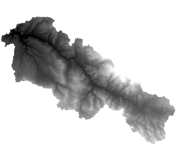
A 10 meter DEM clipped to an area of analysis (HUC 8 Watershed)

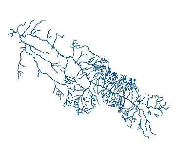
A perennial network prepared using the NHD Network Builder Tool

Output
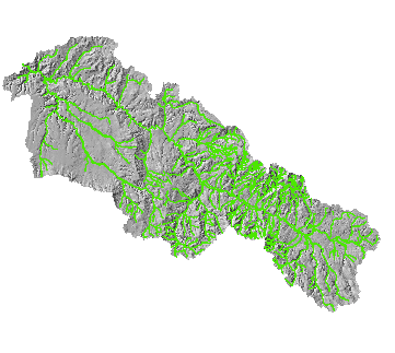
Initial output of the VBET tool for the entire area of analysis

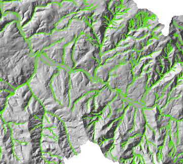
Zoomed in view of the VBET output
